Spine and Leaf Practical Applications, RIPv2
This is only slightly trolling, but is primarily to outline the topological simplicity of Spine-and-Leaf networking, in a way that is suspiciously similar to Cisco classes.
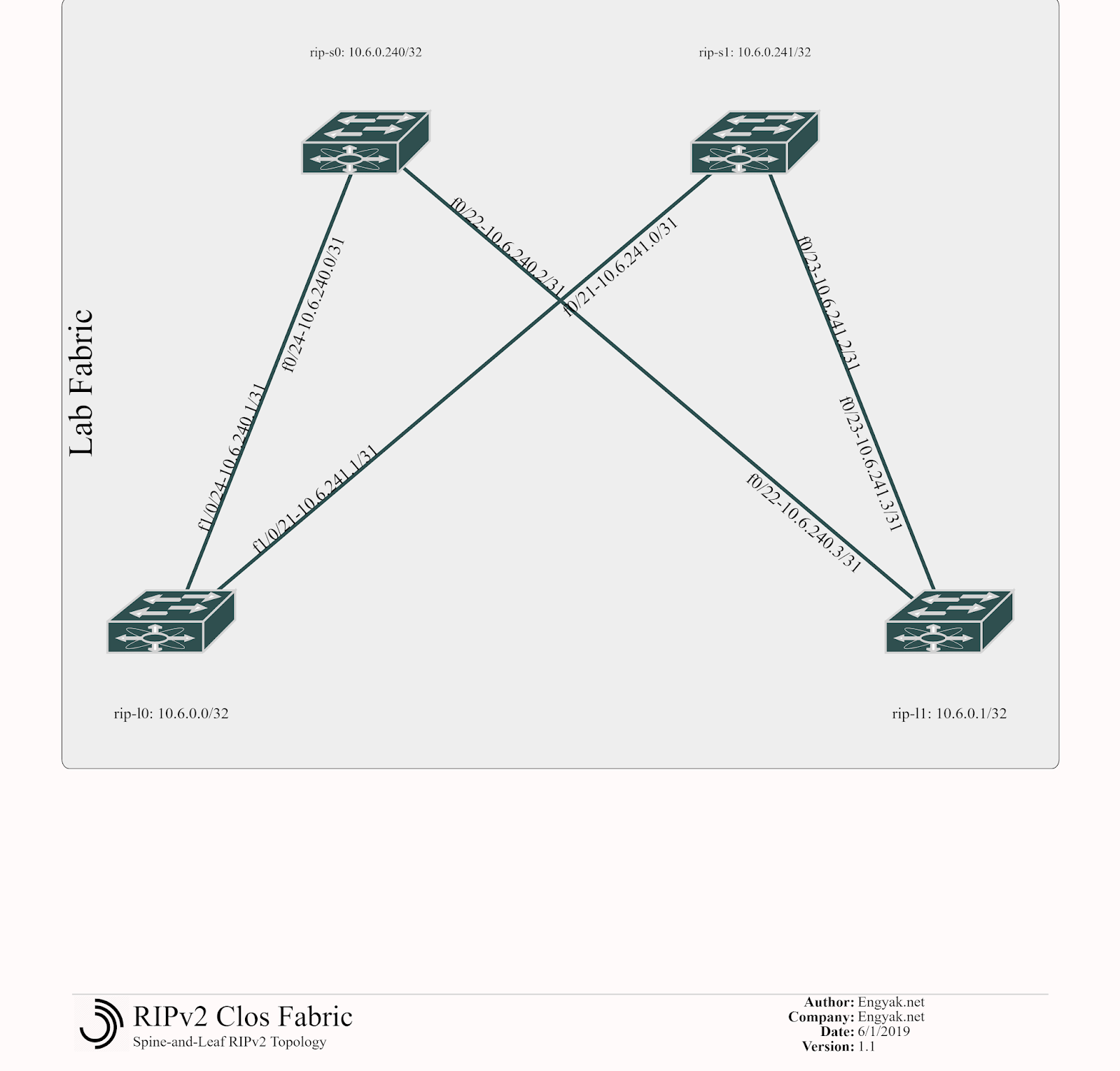
First things first, here's the diagram. This is performed using a set of four Cat3560s, enterprise licensed and wired in a redundant square topology to simulate a wide variety of topologies with minimal modification. At some point I'll post this setup as well, it was recommended in the book CCIE Routing and Switching v5.1, Bridging the Gap Between CCNP and CCIE
YAML Link
So this is actually pretty simple - as everything shouldbe Layer 3. We begin by configuring the Spines:
 1hostname rip-s0
 2interface Loopback0
 3 ip address 10.6.0.240 255.255.255.255
 4interface FastEthernet0/22
 5 no switchport
 6 ip address 10.6.240.2 255.255.255.254
 7interface FastEthernet0/24
 8 no switchport
 9 ip address 10.6.240.0 255.255.255.254
10
11hostname rip-s1
12interface Loopback0
13 ip address 10.6.0.241 255.255.255.255
14interface FastEthernet0/21
15 no switchport
16 ip address 10.6.241.0 255.255.255.254
17interface FastEthernet0/23
18 no switchport
19 ip address 10.6.241.2 255.255.255.254
Some explanation here:
- We're using /31s to save address space as leaf-spine-leaf links are numerous and chew through address space like no tomorrow. If you'd like to know more about /31 usage, it's here.
- I focused on IP Address Management (IPAM) before the actual network design, assigning pre-planned prefixes. In this example, each switch has a virtual number, making it easy to pre-provision and organize network topologies for scale. Remember, this is all to handle frequent loop-free changes at scale - this is important!
- S0: 240 (10.6.240.x/31, 10.6.0.240)
- S1: 241 (10.6.241.x/31, 10.6.0.241)
- L0: 0 (10.6.0.0)
- L1: 1 (10.6.0.1)
- No switchport forces ports into Layer 3 mode.
And then the Leafs:
 1hostname rip-l0
 2interface Loopback0
 3 ip address 10.6.0.0 255.255.255.255
 4interface FastEthernet1/0/21
 5 no switchport
 6 ip address 10.6.241.1 255.255.255.254
 7interface FastEthernet1/0/24
 8 no switchport
 9 ip address 10.6.240.1 255.255.255.254
10
11hostname rip-l1
12 interface Loopback0
13 ip address 10.6.0.1 255.255.255.255
14interface FastEthernet0/22
15 no switchport
16 ip address 10.6.240.3 255.255.255.254
17interface FastEthernet0/23
18 no switchport
19 ip address 10.6.241.3 255.255.255.254
Normally, you'd add interconnection on these devices, but loopbacks suffice for this example.
This doesn't support routing but is a functional base configuration - so let's turn on routing (all switches):
1ip routing
2router rip
3 version 2
4 network 10.0.0.0
5 no auto-summary
Poof! It's working!
 1rip-l0#show ip route
 2Codes: C - connected, S - static, R - RIP, M - mobile, B - BGP
 3   D - EIGRP, EX - EIGRP external, O - OSPF, IA - OSPF inter area
 4   N1 - OSPF NSSA external type 1, N2 - OSPF NSSA external type 2
 5   E1 - OSPF external type 1, E2 - OSPF external type 2, E - EGP
 6   i - IS-IS, su - IS-IS summary, L1 - IS-IS level-1, L2 - IS-IS level-2
 7   ia - IS-IS inter area, * - candidate default, U - per-user static route
 8   o - ODR, P - periodic downloaded static route
 9Gateway of last resort is not set
10  10.0.0.0/8 is variably subnetted, 8 subnets, 2 masks
11C   10.6.0.0/32 is directly connected, Loopback0
12R   10.6.0.1/32 [120/2] via 10.6.241.0, 00:00:06, FastEthernet1/0/21
13          [120/2] via 10.6.240.0, 00:00:06, FastEthernet1/0/24
14C   10.6.240.0/31 is directly connected, FastEthernet1/0/24
15R   10.6.0.240/32 [120/1] via 10.6.240.0, 00:00:12, FastEthernet1/0/24
16C   10.6.241.0/31 is directly connected, FastEthernet1/0/21
17R   10.6.0.241/32 [120/1] via 10.6.241.0, 00:00:17, FastEthernet1/0/21
18R   10.6.240.2/31 [120/1] via 10.6.240.0, 00:00:13, FastEthernet1/0/24
19R   10.6.241.2/31 [120/1] via 10.6.241.0, 00:00:17, FastEthernet1/0/21
Oddly enough, RIPv2 isn't supposed to support ECMP, but appears to be doing so here.
Hopefully, this was enlightening - because in this case, this topology is incredibly simple when involving an IGP. There are a few downsides to RIP deployed in this manner:
- It's chatty and floods all the time, so all changes (network additions) will cause a reconvergence.
- Link-state failure won't trigger a path re-route
- It's RIP.
Configurations generated are here, for anyone who would want to experiment with them.
Posts in this series
- Spine and Leaf Networks, an Introduction
- Spine and Leaf Networks, a Topology
- Spine and Leaf Practical Applications, RIPv2
- Spine and Leaf Practical Applications, OSPF
- Spine and Leaf Practical Applications, eBGP
- Spine and Leaf Practical Applications, EGP and IGP combined!
- Spine and Leaf Practical Applications, The IP Portability Problem
- Spine and Leaf Networks, an Outline